3D Printing Tolerances: Clearances That Actually Fit
You modelled a 6mm hole for a 6mm rod. The rod does not go in. You sanded it, it still does not go in, and now the hole is oval. This is the single most common way a printed part fails, and it is almost never the printer's fault. It is a missing clearance.
Nominal dimensions are a fiction in additive manufacturing. Plastic shrinks as it cools, extrusion has width, and circles get approximated by straight segments. This guide gives the actual numbers to design in, what each process can really hold, and what to tell a maker so the first print fits instead of the third.
What clearance should I design in for 3D printed parts to fit?
For FDM, design 0.3mm of total clearance for a sliding fit, 0.15mm for a snug push fit, and 0.45mm for a joint that must move straight off the build plate. Halve those numbers for MSLA resin. Clearance is total, not per side. A well-tuned desktop FDM machine holds about ±0.2mm on a 50mm feature.
Last verified: July 2026
Key takeaways
- •Clearance is a total diametral figure: a 0.3mm clearance means the hole is modelled 0.3mm larger than the shaft, not 0.3mm larger on each side.
- •A well-tuned desktop FDM printer holds roughly ±0.2mm on a 50mm feature; services that must guarantee it quote ±0.5mm.
- •FDM holes print 0.1 to 0.4mm undersize on diameter because the toolpath sits inside the modelled curve.
- •PLA shrinks about 0.3 to 0.5 percent on cooling, ABS and ASA about 0.7 to 0.8 percent, which on a 100mm part is 0.3-0.5mm versus 0.7-0.8mm of error.
- •Tolerance costs iterations, not material. Budget one reprint of roughly $15 to $40 on any part that has to mate with an existing object.
What Tolerance Can a 3D Printer Actually Hold?
A well-maintained desktop FDM printer holds roughly ±0.2mm on a 50mm feature. That is the honest working number. Print services quote something looser, usually ±0.5mm for desktop-class FDM, because a quoted tolerance is a promise they have to keep across every machine in the shop, every material, and every geometry a customer sends.
Both numbers are true and they are not in conflict. One describes what the machine usually does. The other describes what a business is willing to be held to. If your part genuinely needs ±0.1mm, no amount of asking nicely gets you there on FDM. Change the process or change the design.
Typical dimensional tolerance by process
Desktop FDM lands around ±0.2mm in practice but is quoted at ±0.5mm; MSLA resin is roughly three to four times tighter, and nothing in plastic additive manufacturing approaches machined aluminium.
| process | Typical in practice (± mm) | Commonly quoted (± mm) |
|---|---|---|
| Desktop FDM | 0.2 | 0.5 |
| Industrial FDM | 0.15 | 0.3 |
| Desktop MSLA resin | 0.05 | 0.15 |
| SLS / MJF nylon | 0.15 | 0.3 |
| CNC aluminium | 0.025 | 0.125 |
Source: Manufacturer accuracy specifications and published service-bureau standard tolerance tables, compiled July 2026. Figures are typical values on features under 100mm, not guarantees.
The Clearance Numbers That Actually Work
Design clearance is the gap you deliberately model in, and it is the single lever that decides whether a part fits. The numbers below are diametral, meaning total. If you want a 0.3mm sliding fit on a 6mm shaft, model the hole at 6.3mm, not 6.6mm. Getting this backwards is the second most common failure after leaving no clearance at all.
Resin gets roughly half the clearance because MSLA has no extrusion width to bloom outward and shrinks less during cure. Give a resin part FDM clearances and it will rattle.
Total clearance to design in, by fit type
FDM needs roughly double the clearance of MSLA resin for the same fit. All values are diametral, meaning the hole is modelled larger than the shaft by the full amount shown.
| fit | FDM (mm) | MSLA resin (mm) |
|---|---|---|
| Press fit | 0.05 | 0.02 |
| Snug push fit | 0.15 | 0.08 |
| Sliding fit | 0.3 | 0.15 |
| Print-in-place joint | 0.45 | 0.25 |
| Loose / threaded | 0.6 | 0.35 |
Source: Commonly used FDM and MSLA design-clearance references, July 2026. Starting points to test against, not guarantees; the working figure varies with nozzle diameter and layer height.
The tolerance test that saves the reprint
Before printing anything fit-critical, print a coupon: a 20mm square plate with five holes at the nominal size plus 0.1, 0.2, 0.3, 0.4 and 0.5mm. It takes eight minutes and three grams of filament, and it tells you exactly which clearance your specific printer, material and nozzle produce a working fit at. Any competent maker will do this on request. Ask for it by name.
Why Your Holes Always Print Undersize
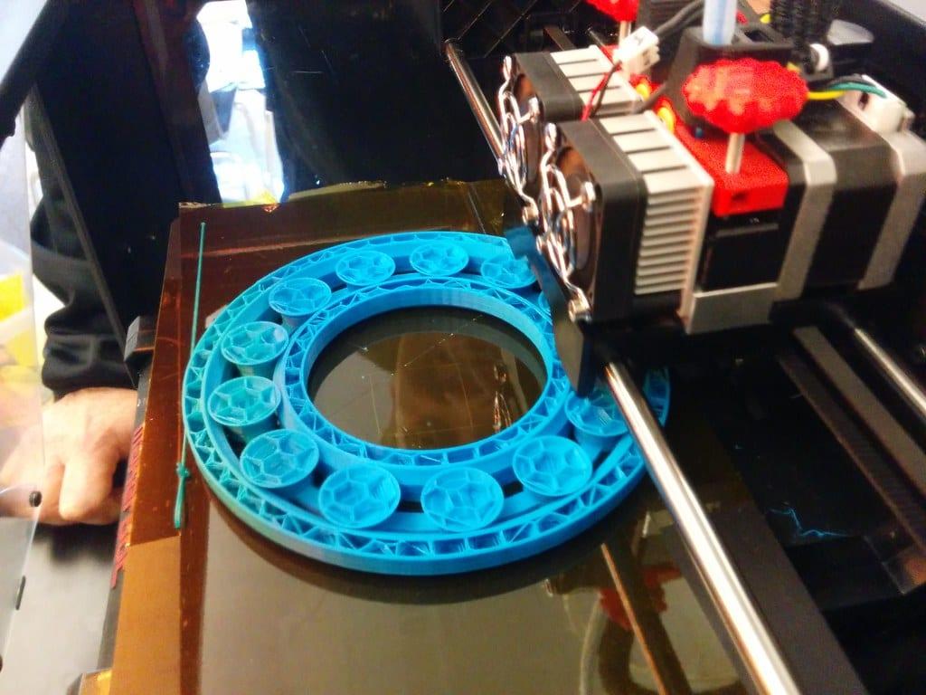
FDM holes come out 0.1 to 0.4mm undersize on diameter, and the effect gets proportionally worse the smaller the hole. The cause is geometric, not a calibration error. A slicer approximates a circle with a series of straight extrusion segments, and those chords sit inside the true curve. The smaller the radius, the more material intrudes into the hole.
Three fixes, in order of how much they cost you. Model the hole 0.2mm oversize, which is free. Ask the maker to enable hole compensation in the slicer, which is also free but depends on their software. Or design the hole undersize on purpose and drill it to size afterwards, which is what you do when the hole must take a bearing or a dowel pin and genuinely has to be round.
Vertical holes suffer this most. A hole printed on its side becomes an entirely different problem, because the top of it needs to bridge across unsupported air and will sag into an egg shape. Where a bore matters, orient it vertically and say so on the order.
Where the Error Actually Comes From
Dimensional error is not one problem. It is four, and they stack. Knowing which one is biting you decides whether the fix is a slicer setting, a material change or a redesign.
| Error source | Typical magnitude | What fixes it |
|---|---|---|
| Thermal shrinkage | 0.3–0.5% PLA, 0.4–0.6% PETG, 0.7–0.8% ABS and ASA, 1–2% nylon | Choose PLA or PETG for fit-critical parts, or scale the model up by the material's shrinkage figure |
| Elephant's foot | 0.1–0.3mm bulge on the bottom one or two layers | Slicer first-layer compensation, or a 0.5mm chamfer on the bottom edge |
| Hole chord error | 0.1–0.4mm undersize on diameter, worse below 5mm | Model 0.2mm oversize, or drill to final size after printing |
| Extrusion width variation | 0.05–0.15mm on external walls | Flow calibration on the maker's side; nothing you can do in the model |
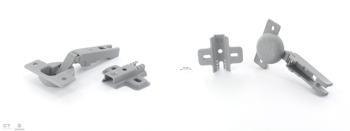
Shrinkage is the one people forget, and it is the one that scales. A 0.5 percent error is 0.1mm on a 20mm part and nobody notices. On a 200mm part it is 1mm, and the lid no longer fits the box. If your part is large and has to mate with something, say so upfront so the maker can compensate rather than discover it at the end.
What Tighter Tolerances Cost You
Tolerance does not show up as a line item on a print quote, because the material cost of a precise part and a sloppy one is identical. What it costs is iterations. A part that has to mate with an object you already own is a two-print job more often than a one-print job, and the second print is the fee you are really paying.
On a small part that second iteration is roughly $15 to $40 including the maker's handling time. You can price the material side of any variant yourself with our 3D printing cost calculator, and our full 3D printing cost guide breaks down where the rest of a quote goes.
The way to avoid paying twice is to make the first print correct by design. Send measurements rather than assumptions, tell the maker what the part mates with, and give them permission to print a test coupon before committing to the full part. A coupon costs three grams. A reprint costs a week.
What to Tell Whoever Prints It
A maker cannot infer intent from an STL. The file says a hole is 6.00mm. It does not say whether a 6mm steel rod must slide through it, press into it permanently, or never touch it at all. Those three cases want three different hole sizes, and the difference between them is over half a millimetre.
Send these four things and the fit question mostly disappears:
- Which dimensions are critical, by name. "The 6mm bore and the 48mm bolt spacing must be right; everything else can drift."
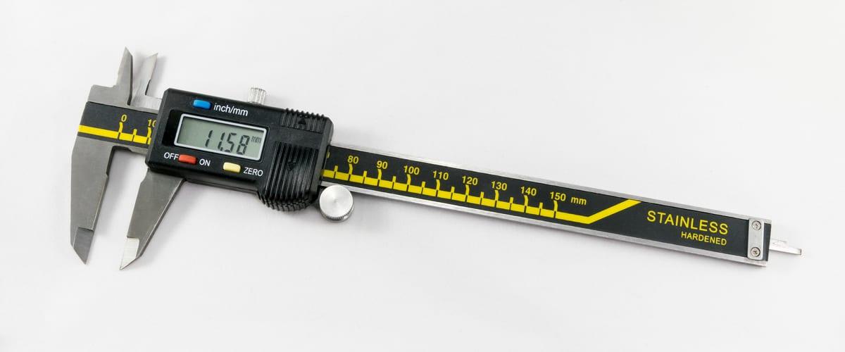
- What each critical feature mates with, measured with calipers. A bearing part number is even better than a measurement.
- The fit you want in words: press, snug, sliding or free. Makers convert that to a number faster than you can.
- Whether post-drilling is acceptable. If it is, you have just made a hard part easy and probably saved a reprint.
One more thing worth saying plainly: if a part needs better than ±0.1mm on a functional feature, FDM is the wrong process and a good maker will tell you so. Resin gets you closer. Printing a part and having the critical bore machined afterwards gets you all the way. A maker who promises ±0.05mm on a desktop FDM machine is guessing.
Frequently asked questions
What tolerance can a 3D printer hold?
A well-tuned desktop FDM printer holds about ±0.2mm on a 50mm feature. Print services that have to guarantee the number quote ±0.5mm for desktop FDM. Desktop MSLA resin is roughly three to four times tighter, around ±0.05 typical against ±0.15mm quoted. Nothing in consumer 3D printing approaches machined metal, which is routinely ±0.025mm.
How much clearance should I leave between two 3D printed parts?
Leave 0.3mm of total diametral clearance for a sliding fit on FDM, 0.15mm for a snug push fit, and 0.45mm for a joint that must move straight off the build plate. On MSLA resin halve those figures. Clearance is total, not per side, so a 0.3mm clearance means the hole is 0.3mm larger than the shaft.
Why do my 3D printed holes always come out too small?
FDM printers approximate a circle with straight extrusion segments laid inside the nominal curve, so a modelled hole prints 0.1 to 0.4mm undersize on diameter. It gets worse on small holes and on the first few layers, where squish widens the extrusion. The standard fix is to model holes 0.2mm oversize, or to drill them afterwards.
Does material choice change the tolerance I get?
Yes, mostly through shrinkage. PLA shrinks roughly 0.3 to 0.5 percent as it cools, PETG 0.4 to 0.6 percent, and ABS or ASA 0.7 to 0.8 percent. On a 100mm part that is 0.3 to 0.5mm of error in PLA against 0.7 to 0.8mm in ABS, before anything else goes wrong. Order fit-critical parts in PLA or PETG unless heat resistance forces otherwise.
Do tighter tolerances cost more to print?
Yes, but not through the printer. Material cost barely moves. What you pay for is a test coupon, a first article, and the maker resizing the model and reprinting when the first fit is wrong. Budget one extra iteration, roughly $15 to $40 on a small part, whenever a printed part has to mate with something you already own.
Get a Part That Fits the First Time
Post your model with the critical dimensions called out and what they mate with. Makers who do fit-critical work will bid, and your payment stays in escrow until you have approved photos of the finished part.